Details on how to build the simple astro tracker I used for my photos of Comet Hale Bopp. This design is based on one which appeared in Astronomy and also a manual version in "Norton's 2000" the amateur astronomers bible.
Firstly the basic principle
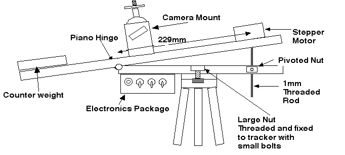
This Barn Door Tracker is based on two hinged wooden slabs connected by an winding screw thread. Provided the rate of rotation, pitch of the screw thread and its distance from the hinge is correct then the rate of rotation of the camera mount will match the rotation of the Earth and will stabilise the mount against this rotation for some minutes. To make this all happen the hinge of the Barn Door needs to be aligned with the Pole Star for Northern Hemisphere photographers or the southern celestial pole for those south of the equator (not such an easy task I am lead to believe).
Stepper motor Circuit Diagram taken from the November 1992 edition of Astronomy magazine.
I assembled the circuit on strip board and mounted it in a small box with the three control switches mounted on one side with the LED. Power is supplied from a small sealed Lead/acid 12V rechargeable cell from Maplin in the UK but available from all good electrical/electronic suppliers. I obtained the main driver chip from Farnell electronic suppliers.The main modification to the basic design that I made was to incorporate a counter weight on the top board to account for a lower power stepper motor and to balance different camera kit on the ball mount.
To simplify the device so that it requires no electronics at all remove the stepper motor and it's accessories and fit a wire to the lower end of the screw thread. A thick wire that you can use to rotate the thread at the same rate as the second hand of a watch this will allow tracking as before.